Harish Projects
12V Relay Coil
12V Relay Coil
Couldn't load pickup availability
Share
Specification
- Voltage : 12V DC
Description
A 12V relay coil is an essential component in electronic circuits that allows low-voltage signals to control higher-voltage devices or systems. The coil in a 12V relay is designed to operate when a 12V DC (direct current) voltage is applied to it. Here’s a simple representation of a 12V relay coil symbol:
____
A+ | | A-
| |
—-
In the symbol:
A+ and A- represent the coil terminals.
When a 12V DC voltage is applied across the A+ and A- terminals, a magnetic field is generated within the coil, activating the relay.
When the relay coil is energized, it can switch the position of internal contacts, allowing or interrupting the flow of current through the relay. This switching action is commonly used for various applications, such as controlling lights, motors, or other electrical devices in response to a low-voltage signal.
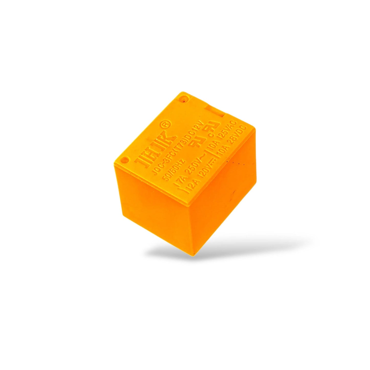
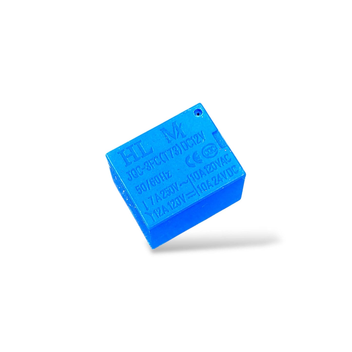
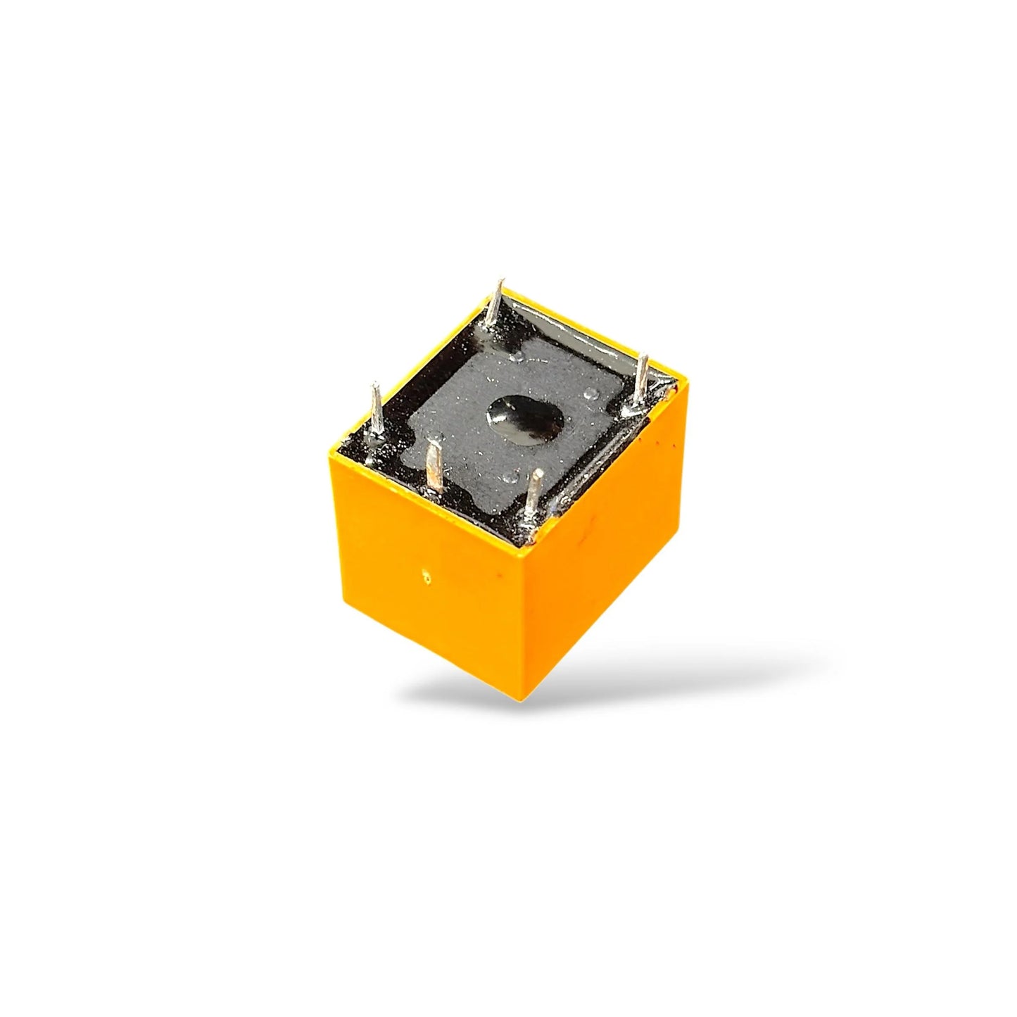
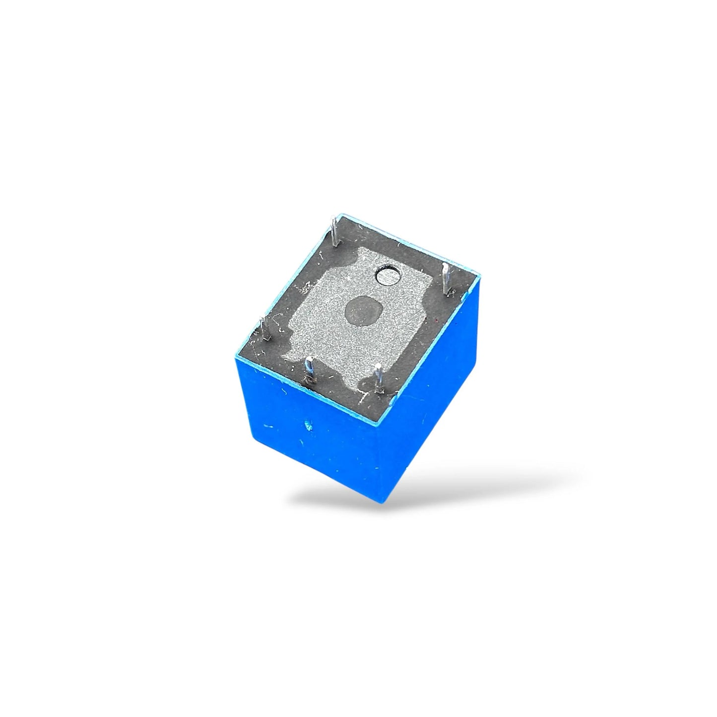
Keep in mind that the actual physical appearance of a 12V relay may vary depending on the manufacturer and specific model. It typically includes the coil and a set of contacts that change state when the coil is energized.
The specifications of a 12V relay coil can vary depending on the specific model and manufacturer. However, I can provide you with a general overview of the typical specifications you might find for a 12V relay coil:
Voltage Rating: The coil is designed to operate with a specific voltage, in this case, 12 volts DC. This means that the relay will be activated when a 12V DC voltage is applied across its coil terminals.
Coil Resistance: The coil resistance is measured in ohms and represents the opposition the coil presents to the flow of current. It’s a crucial factor in determining the current flowing through the coil when the rated voltage is applied.
Power Consumption: This is the amount of power (in watts) consumed by the relay coil when it is energized. It is calculated using the formula: Power (Watts) = Voltage (Volts) x Current (Amperes).
Pull-In Voltage: This is the minimum voltage required to reliably activate the relay coil and close its contacts.
Drop-Out Voltage: This is the maximum voltage that can be applied across the coil terminals while keeping the relay contacts in the open position.
Maximum Continuous Voltage: The maximum voltage that can be continuously applied to the relay coil without causing damage.
Duty Cycle: Some relays may have specifications regarding the duty cycle, indicating the percentage of time the relay can be energized versus the total cycle time.
Temperature Range: The range of temperatures within which the relay can safely and reliably operate.
Insulation Class: This indicates the insulation rating of the relay coil, which is important for determining its suitability for specific environmental conditions.
Always refer to the datasheet provided by the relay manufacturer for precise information on these specifications, as they can vary. The datasheet typically includes detailed electrical characteristics, mechanical dimensions, and other important information about the relay.


